
As alkaline water electrolysis (AWE) and anion exchange membrane electrolysis (AEMWE) scale up for green hydrogen production, stack efficiency and energy consumption become core commercial differentiators. A large share of excess voltage in electrolyzer stacks originates from ohmic resistance, which directly raises power draw and reduces system economics. Nickel felt, a sintered non-woven porous transport layer (PTL), has become a preferred substrate for alkaline electrolyzer anodes and cathodes, balancing high electrical conductivity, alkaline corrosion resistance, and tunable porous architecture. This article breaks down nickel felt's conductive behaviour, root causes of ohmic loss, and practical material and stack design strategies to minimise cell resistance for high-current-density electrolysis.
Ohmic loss follows Ohm's law: voltage drop = current × total cell resistance. Total ohmic resistance is not only from the bulk nickel fibre network. It combines three components: bulk resistance of the sintered nickel felt, interfacial contact resistance between felt, catalyst layer, and bipolar plate, and ionic resistance impacted by gas bubble trapping within the porous structure. For industrial electrolyzers running at elevated current densities, even small reductions in area-specific ohmic resistance translate into measurable electricity savings and improved hydrogen yield per kilowatt-hour.
The Conductive Nature of Sintered Nickel Felt
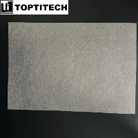
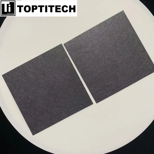
Nickel felt is manufactured by sintering randomly arranged nickel fibres into a self-supporting, flexible porous medium. Unlike continuous solid nickel sheet or woven nickel mesh, electrical conduction occurs through point-to-point sintered junctions between overlapping nickel fibres. Pure nickel metal possesses excellent intrinsic electrical conductivity; however, the effective through-plane conductivity of nickel felt is downgraded by its high porosity and fibre junction contact quality. Typical nickel felts for electrolyzer applications feature porosity ranging from 70 % to 90 %, with custom thickness and areal density tailored to target conductivity and mass transport performance.
The sinter bonding step is critical for electrical performance. Inadequate sintering leaves weak fibre contacts, which increase sheet resistance and cause performance drift under stack clamping pressure and thermal cycling. Well-sintered nickel felt maintains stable electronic pathways across the entire PTL, delivering consistent in-plane and through-plane conductivity. Compression during stack assembly also changes effective conductivity: moderate compression tightens fibre contact points and lowers contact resistance. Over-compression closes pore channels, hinders gas bubble release and raises ionic resistance, creating a performance trade-off that every electrolyzer designer must balance.
Nickel felt stands out in alkaline environments compared with alternative porous substrates. Stainless steel suffers corrosion in concentrated KOH electrolyte, while carbon-based materials cannot withstand alkaline anodic conditions. Nickel forms a stable passive oxide/hydroxide layer that protects the fibre network, preserving long-term electrical connectivity during thousands of operating hours. This chemical compatibility makes sintered nickel felt the default PTL selection for AWE and AEMWE stacks targeting low maintenance and long service life.

Main Sources of Ohmic Loss in Nickel Felt Electrolyzer Assemblies
Many engineers mistakenly attribute ohmic loss solely to the PTL material itself. In operational electrolyzers, interfacial contact resistance often dominates total ohmic loss. The fibrous surface topography of nickel felt creates discrete contact points against bipolar plates and catalyst coatings. Poor surface flatness, inconsistent fibre exposure or uneven catalyst infiltration creates high-resistance gaps at these interfaces. When current density rises, localised hotspots emerge, accelerating material degradation and further increasing series resistance over time.
A second major contributor is gas bubble blockage within the felt pore network. During water electrolysis, hydrogen and oxygen bubbles nucleate on the electrode surface and migrate through the porous felt. Trapped gas displaces liquid KOH electrolyte, reducing ionic conductivity and increasing local ohmic drop. Nickel felt's open 3D fibrous structure helps release bubbles, but pore size, tortuosity and wettability must be optimised. If pores are too fine, bubble accumulation becomes severe at high current densities, pushing up high-frequency resistance measured by EIS (Electrochemical Impedance Spectroscopy).
Third, bulk through-plane resistance of nickel felt depends strongly on fibre diameter, sinter quality and material thickness. Thicker felt improves mechanical compliance and catalyst loading capacity, but adds longer electron transport paths and higher bulk resistance. Thinner grades cut ohmic drop yet sacrifice compressibility and active surface area. This is the core material optimisation dilemma for nickel felt PTL specification.
Practical Strategies to Reduce Cell Resistance with Optimised Nickel Felt
1. Tune sintering quality and fibre morphology
Controlled sintering maximises metallurgical bonding at fibre crossover points, lowering the sheet resistance of nickel felt. TOPTITECH can adjust fibre diameter and distribution to build a robust conductive skeleton while retaining high porosity. Fine nickel fibres boost electrochemically active surface area for catalyst anchoring; coarser fibres deliver stronger conductive pathways and better mechanical stability. Custom fibre blends are widely used to balance conductivity, surface area and bubble removal capability.
2. Optimise stack compression and interface engineering
Controlled clamping pressure enables nickel felt's conformable fibrous structure to conform to catalyst layers and flow fields, reducing interfacial contact resistance. Pre-treatment processes such as surface flattening, plasma treatment or nickel micro-coating can smooth surface peaks and valleys, expanding effective contact area. These treatments reduce ICR (interfacial contact resistance) significantly without fully blocking pore channels for electrolyte and gas transport.
3. Match porosity and pore structure to operating current density
Low-tortuosity pore architecture accelerates gas bubble escape and maintains electrolyte continuity inside the felt. For high-current-density AEMWE, nickel felt grades with tailored pore size distribution minimise gas holdup and stabilise ionic conductivity. Material selection must align with electrolyte concentration, operating temperature and differential pressure across the cell.
4. Pair nickel felt with compatible catalyst deposition
Nickel felt's 3D fibrous matrix supports deep penetration of NiFe or Ni-based catalyst inks. Uniform catalyst infiltration reduces contact resistance between the conductive nickel substrate and catalytic phase. Partial catalyst loading that only coats the felt surface creates a high-resistance boundary layer, whereas properly infiltrated structures maintain continuous electron flow from fibre network to active catalytic sites.



Conclusion
Ohmic loss remains one of the largest controllable energy drains in alkaline and anion exchange electrolyzers. Nickel felt's electrical performance is governed not only by nickel's intrinsic metal conductivity, but by sintered fibre junction quality, interfacial contact conditions, pore geometry and bubble dynamics. Selecting a properly engineered sintered nickel felt PTL, paired with optimised stack compression and surface treatment, directly cuts area-specific cell resistance, lowers operating voltage and improves green hydrogen production efficiency.
As electrolyzer OEMs continue pushing to higher current densities, nickel felt material specification will grow more critical. Tuning conductivity and ohmic behaviour at the PTL level is a cost-effective route to enhance stack performance, reduce operational expenditure and improve the commercial viability of green hydrogen projects.