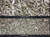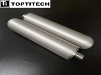

A multilayer sintered part is built from two or more layers of woven wire mesh, metal fiber felt or powder sintered sheet, consolidated in one or more sintering cycles into a single body. No adhesive, braze alloy or solder sits between the layers, and no third material appears anywhere in the stack. The bond comes from solid-state diffusion, in which atoms on both sides of the interface interdiffuse and rearrange below the melting point of the alloy, so that the original interface becomes a grain boundary.
Every layer in a given part is the same alloy, either titanium throughout or austenitic stainless steel throughout; the two are fired on separate lines, no titanium-to-steel joint exists anywhere in the product range, and what follows applies to both.
Whether such a part holds together turns on three questions, namely what sets the strength of a joint, why a part whose layers are bonded still lifts at its rim, and why flow through an assembly falls short of the sum of the layers measured one at a time.
1. Why the joint forms below the melting point
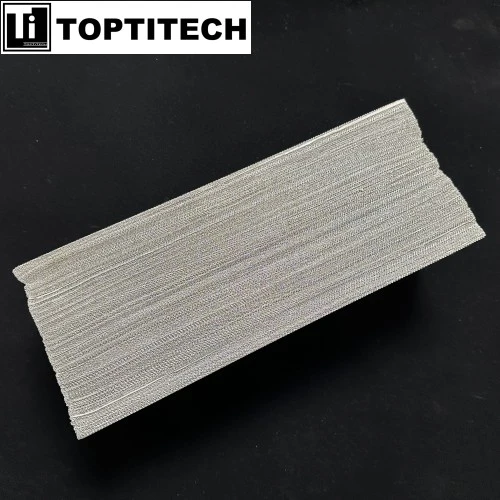
Titanium melts at 1668 °C, austenitic stainless steel between 1370 and 1450 °C. Sintering runs well below either figure, and the alloy stays solid for the whole cycle, so no liquid phase is available to act as a binder. Nothing is put in the gap, and the joint section comes out base metal from one face to the other.
Three conditions have to hold together:
the two faces come within a few tenths of a nanometre, where the metallic bond acts;
the interface is clean, with no continuous oxide film or other diffusion barrier;
atoms are mobile, which temperature provides and time sustains.
If any one of the three is missing, the layers remain in physical contact without a metallurgical bond. Sections 4.1 to 4.3 treat the three ways this arises.
When all three hold, atoms cross the interface and one lattice spans it. The old interface becomes a grain boundary, and that boundary can migrate as diffusion continues. A grain boundary is part of the metal, since rolled sheet and drawn wire consist of grains and boundaries already, and a boundary carries load at the same order as the grains beside it. Fracture position and fracture appearance both follow from that structure.
2. The sintering neck and joint strength
Wire meets wire along a line and particle meets particle at a point. The geometric contact area is then a small fraction of the apparent section, and the load-bearing section at the start of the cycle is close to zero, although the stack already has its final dimensions.
Curvature at the contact is the tightest in the system and surface energy the highest, so atoms leave the flatter surfaces and pile up at the contact. The result is a body thick at both ends and thin in the middle, the sintering neck (standard powder metallurgy term for the diffusion-formed connection between touching particles or wires). Surface diffusion, grain-boundary diffusion and volume diffusion all feed the neck, and which of the three dominates depends on temperature and time.
Once a neck exists, the connection between two particles changes from geometric contact to continuous lattice. Growth widens the contact section, and the pore channels spheroidise and shrink under surface tension. In a powder body, neck growth shortens the centre-to-centre distance and the part shrinks as a whole. Mesh and felt shrink far less, because their fibers are already dense before firing and the neck serves only to connect them. That difference is where residual stress enters when two forming routes are combined (4.3).
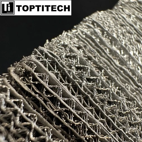
Strength follows the neck section as a fraction of the original, in tension and in shear alike. A neck grown to a third of the particle diameter offers about a ninth of that particle's section. Neither the layer count nor the mesh specification enters that figure.
Batch scatter follows from the same geometry, because the drawing fixes the mesh specification and the layer order, while the neck forms only in the furnace, and neither visual inspection nor a dimensional check reports its size.
3. Adhesive and sintered joints compared
The obvious comparison is adhesive, and the difference that matters lies in what occupies the joint, a polymer layer in one case and base metal continuous with both sides in the other.
|
Adhesive |
Sintered joint |
|
|
Material in the joint |
polymer layer, a third phase |
none, base metal meets base metal |
|
Interface |
adhesion face with a material step |
grain boundary, one lattice |
|
Load path |
through a 0.1–0.2 mm polymer layer, which carries the load in shear |
through the lattice |
|
Service limits |
temperature ceiling, solvents, extractables |
limits of the alloy itself |
Brazing belongs outside that comparison. Its interface is built from a filler of different composition, with a material step and intermetallic phases, so although the joint is metallurgical, bonding one alloy to itself raises a different set of problems.
Whether the interface is the weakest point depends on neck size. With an undersized neck, fracture runs along the original stacking plane. The face stays flat, shows almost no necking, and the layer boundary is still visible. With a full neck, fracture moves into the wire or into the particle, and the face comes out rough with the metal deformed. Where the break occurs identifies the weakest section in the assembly, which is what a fracture test is asked to establish.
Macroscopic elongation of a porous sintered body is low, so the position of the break carries more information than its texture. Dimple morphology requires a microscope, whereas the distinction between a flat face and a rough one does not. The check is destructive and is run on a coupon from the same batch.
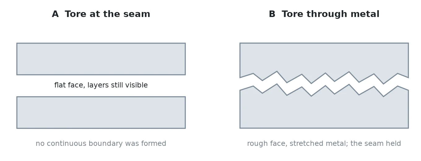
Position and texture of a fracture. Left: fracture along the original stacking plane, flat face, no necking, layer boundary still visible. Right: fracture through wire or particle, rough face with plastic deformation. (Schematic, not to scale.)
4. Three causes of an incomplete joint
Three mechanisms leave an interface short of a continuous boundary, and each calls for a different correction. The first two give a part that measures correct and passes a leak test. The third leaves a bend that starts at the rim.
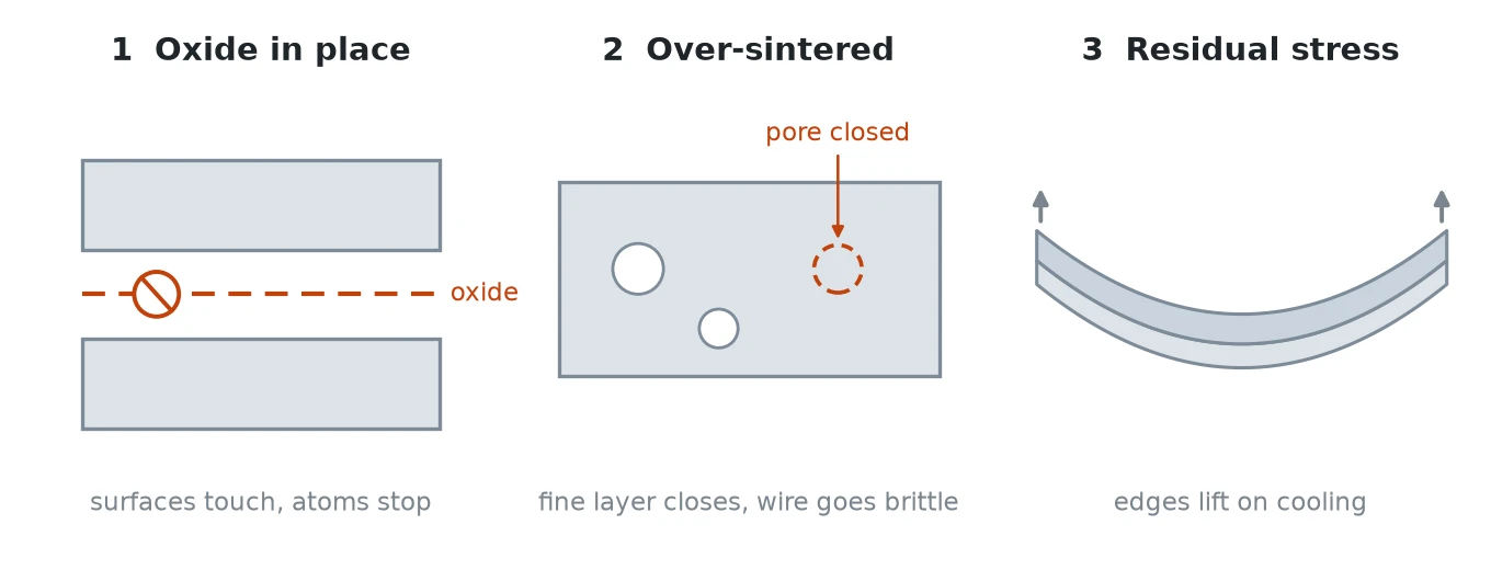
Oxide left at the interface, over-sintering of the fine layer, and differential shrinkage between layers. The first two hold dimension and pressure; the third shows as a bend starting at the rim. (Schematic, not to scale.)
4.1 Oxide at the interface
Metal surfaces carry an oxide film in normal conditions, and the film blocks interdiffusion. Vacuum or high-purity inert gas stops further oxidation, and it lets the existing film dissolve until the two surfaces are clean.
Titanium is harder to clean in this respect, because TiO₂ is thermodynamically stable and hot titanium holds oxygen in solid solution to a high level, so a film on titanium leaves by dissolving into the metal, and reduction plays little part in removing it. A titanium interface needs a tighter atmosphere than a stainless one, and conditions proven on stainless steel do not transfer to it.
In this condition the interface is in contact, the part meets its dimensional tolerance and holds pressure, and no continuous grain boundary exists across the joint. Pressure drop runs high, or flux runs low along one strip of the surface. Routine inspection does not detect it, whereas a section or a non-destructive scan does.
4.2 Over-sintering
Heat and time past the limit take the fine layer first. Pores close, wire grains coarsen and embrittle, and a wire can pinch through. The joint is strong by then, but the rating and the flux have moved, and the part still looks right on the bench.
A multilayer stack runs into a conflict here, since the finest layer wants the lower temperature that keeps its pores open while the coarsest wants the higher temperature that grows a neck. The two requirements sit at opposite ends of the temperature axis, the usable window is their overlap, and that overlap is narrow. A stack therefore tolerates furnace non-uniformity less well than a single layer does.
4.3 Residual stress
Layers formed by different routes shrink by different amounts. Wire and fiber are already dense, so their shrinkage comes mainly from the contact points and stays small. A powder sheet densifies through particle rearrangement and neck growth, and its linear shrinkage is far larger.
After cooling, the interface carries residual stress, and the rim has the least constraint and the highest concentration. Back-pulsing and pressure swings then apply the cycle, so a crack opens at the edge and each cycle extends it until the layers come apart.
Here the joint formed, and what exceeds its capacity is the stress carried across it, which means the two available corrections address different causes. Structural measures come first and take the form of a rolled edge, a dense rim or a graded transition between layers. Changes to the firing schedule address the other cause, and applied to this one they leave the stress in place.
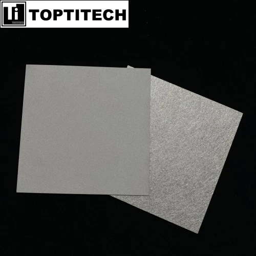
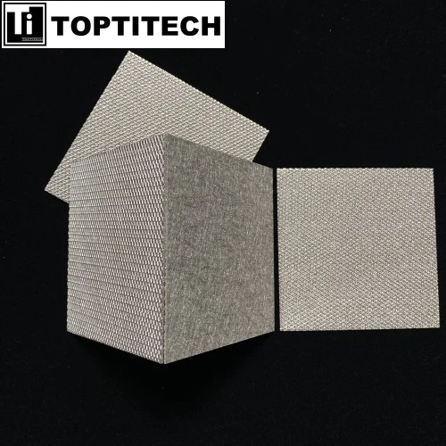
5. Interface geometry and pressure drop
A bonded interface does not necessarily pass fluid freely. Where mesh is bonded to powder sheet, the openings of the mesh form a regular grid while the sheet carries irregular three-dimensional channels, and an opening in the upper layer often faces solid material in the lower one. The area available to flow is set, to a first approximation, by the overlap of the two opening patterns, with the tortuosity of the connected path entering as additional resistance.
An interface therefore adds resistance of its own, and measured pressure drop across an assembly commonly lands above the figure obtained by adding the layers tested separately, the difference accumulating at each interface in the stack.
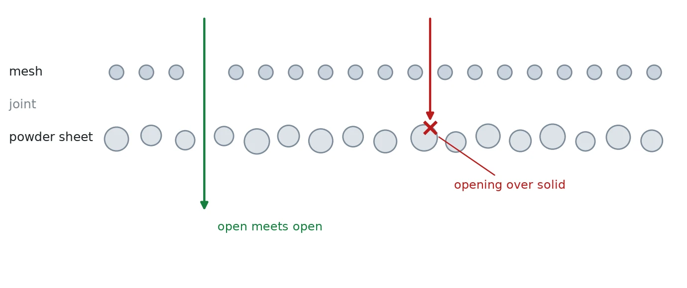
An opening in the upper layer has to land on an opening in the lower one. Where it lands on solid material, the interface carries no flow at that patch, so the joint adds resistance between two open layers. (Schematic, not to scale.)
Permeability measured on a single layer does not predict the pressure drop of a composite, and the gain from an added layer has to be assessed with the interface resistance subtracted.
6. What can be checked
The layer count does not indicate whether a joint is under control; the three items below do.
How the window for the fine layer was fixed. Whether the overlap between the permitted ranges of the finest and the coarsest layer was quantified, or simply taken from single-layer experience.
How joint strength is evaluated. Tensile, shear or ultrasonic data. Appearance and a leak test do not count.
How distortion is controlled when forming routes are combined. Felt over sheet and mesh over sheet carry the largest shrinkage difference, and an answer here should name a structure or a fixture.
Conclusion
A multilayer sintered part holds together through solid-state diffusion. Whether it is genuinely one body turns on a continuous grain boundary at each interface, a neck section sized for the load, and residual stress absorbed by the structure. Each of the three can be measured, or inferred from a sample, and none of them appears in the layer count.