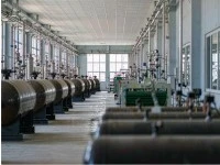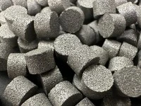

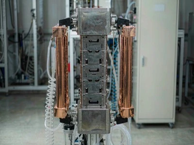
Two titanium pieces fit on the anode side of a PEM electrolyser stack. One piece is the bipolar plate. It keeps neighbouring cells separated. The other piece is the porous transport layer, or PTL. It fills the gap between the bipolar plate and catalyst-coated membrane. Makers discard a bipolar plate if any break runs fully through its thickness. Makers discard a PTL if its connected hole network does not pass all the way through. These two rules are not optional. Both rules come from reactions at the oxygen-making electrode.
The anode environment
Water breaks into oxygen, protons and electrons at the anode. The electrode runs above the oxygen evolution voltage. It touches acidic ionomer and water loaded with oxygen. Fresh oxygen and peroxide intermediate products form during all operating time.
Most metals dissolve under these working conditions. Or they build thick corrosion layers until the part fails. Titanium forms a thin TiO2 film instead. This film forms on its own. It grows again fast if the film gets damaged. This trait makes titanium the chosen material. This oxide film does not carry electricity well. Every titanium surface on the anode side adds extra resistance. This resistance does not come from the titanium metal underneath.
This single trait shapes most engineering work for anode-side titanium. Coatings, surface treatments and sintering methods share one core goal. They keep the oxide film intact to stop corrosion. They also limit extra electrical resistance. Engineers cannot remove this conflict fully for any single part. They only bring it down to a workable level.
Bipolar plates
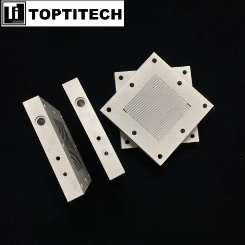
A bipolar plate splits hydrogen space and oxygen space of nearby cells. It moves electric current between cells. It spreads water and gas through carved flow paths. The separation task sets quality check rules. Any continuous opening through the plate lets hydrogen mix with oxygen.
The starting material is fully solid titanium strip. Its thickness sits at a few tenths of one millimetre. Makers stamp the strip to shape flow channels. Inspectors check three key points. They look for tiny holes in the strip. They check thin wall sections and small cracks at channel corners. They test weld strength if workers join multiple pieces to build one plate. Every bipolar plate goes through leak testing before acceptance.
Contact resistance creates another hard limit. Platinum or iridium-based coatings bridge the oxide film. Bipolar plates take a large share of total stack cost. Makers keep pushing to make these coatings thinner. Recent lab work reports platinum coatings of tens of nanometres. Current mass production uses coatings of hundreds of nanometres. These test results depend on coating deposition methods. Full coverage across flow paths and base material quality matter as much as stated coating thickness. Thin coatings often break at edges and channel bottoms. This failure happens long before the whole coating fails.
Porous transport layers
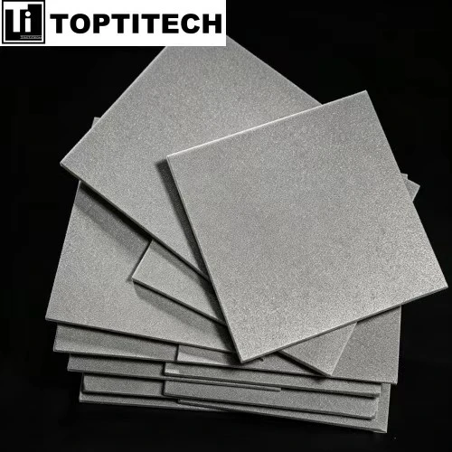
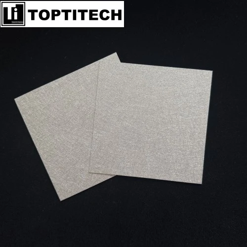
The PTL fills the space between the bipolar plate and catalyst layer. One working PTL handles four jobs at the same time. It carries electric current from the plate into the catalyst layer. Resistance builds through its thickness and at both contact faces. It sends water toward the catalyst. It pulls oxygen away from the catalyst. It holds the catalyst layer and membrane steady under stack compression force. It spreads compression force evenly. This keeps steady contact pressure across the active area.
These jobs work against one another. Higher porosity lets water move in and gas move out easily. But higher porosity cuts conductive material and mechanical strength. Lower porosity gives the opposite effect. A PTL specification is a group of values set for one fixed working condition. People cannot describe a PTL using porosity number alone.
Oxygen removal often sets the real performance limit. Trapped gas inside holes blocks catalyst sites. It raises local voltage and cuts system efficiency. The hole structure must let gas bubbles separate and shift toward flow paths. A hole structure that traps bubbles at the contact face shows up on polarisation curves. This problem appears before any porosity test picks it up.
Sintered plate and felt
The two common PTL types create empty holes in different ways. Most property differences come from this core difference.
| Property | Sintered titanium plate | Titanium fibre felt |
|---|---|---|
| Pore formation | Empty gaps between powder grains after sintering | Empty gaps between woven overlapping fibres after sintering |
| Pore size control | Set mainly by powder grain size range; narrower size spread | Set by fibre width and material weight per area; more twisting hole paths |
| Porosity | Medium porosity, higher solid body density | Higher porosity, better flow for gas and liquid |
| Thickness | Can be made thin. It works well for thin-PTL designs | Usually thicker. Thin versions are hard to manufacture |
| Mechanical behaviour | Stiff. Large-area cracking during sintering is a known issue | Yielding. It stands compression and temperature shifts better |
| Typical limitation | Brittle. Edge chipping happens easily | Higher through-plane resistance. Fibre raw material costs more |
Engineers pick PTL types based on stack design, not simple ranking. Teams select sintered plates when low ohmic loss and thin cell layout are top priorities. Teams select fibre felt when yielding behaviour, high porosity and pressure cycle tolerance matter most. Hybrid builds use two stacked layers. A fine-pore layer sits next to the membrane. It delivers contact support and stops membrane puncture. A coarse-pore layer sits toward flow paths. It helps liquid drain away.
Where suppliers differ
Laboratories can make small batches of PTL with acceptable porosity and resistance. Suppliers can easily send small sample pieces with this quality. Real gaps between suppliers show up in mass production batches. Makers must keep pore size range, porosity, thickness and surface condition inside target limits. Small shifts to any of these four factors change stack performance.
Buyer documents often miss four important details.
Edge quality. The PTL touches the membrane directly. Sharp burrs and chips from cutting or laser trimming can puncture the thin membrane. The membrane thickness is only tens of micrometres. This damage cannot be fixed during assembly.
Surface condition. Sintering leftover material and machining dirt raise contact resistance. Cleaning and acid pickling steps carry equal weight with forming work. These cleaning steps are also hard to audit.
Passive layer thickness. All titanium pieces used on the anode grow a thin oxide skin. If makers fail to control its thickness, the film adds series resistance inside the cell. People usually link this extra resistance to the surface coating.
Coating coverage on a three-dimensional surface. Coating inner hole surfaces is harder than coating flat titanium strip. Hole walls without coating act as bare titanium.
Development directions
Three main research tracks exist for anode-side titanium materials. These tracks differ mainly in where cost savings will come from.
Thickness reduction cuts ohmic loss and raw material use. Strength limits this method. The material must still hold up under compression force. The structure also needs space for two-phase liquid and gas flow. Performance gains slow down long before thickness hits the minimum possible value.
Graded pore structures change pore size and porosity through the full material thickness. Different depths handle contact, mass transport and drainage separately. Most experts expect this track to bring the largest performance gains. Progress depends on precise production control. Material choice plays a smaller role here.
Precious metal reduction covers three areas. Makers produce thinner coatings on bipolar plates. They lower precious metal loading on PTL surfaces. Researchers also test non-precious alternatives. Titanium carbide and titanium nitride are two examples. Cost moves away from expensive coatings. The cost shifts to material structure and manufacturing steps.
All three research tracks need one core ability. Makers must control pore structure. They must prove this control stays stable during mass production. Stack service life reaches tens of thousands of working hours. Most published PTL property data only comes from the first few hundred hours of testing. A measurement taken at hour zero cannot predict material performance at hour 5,000.